Introduction
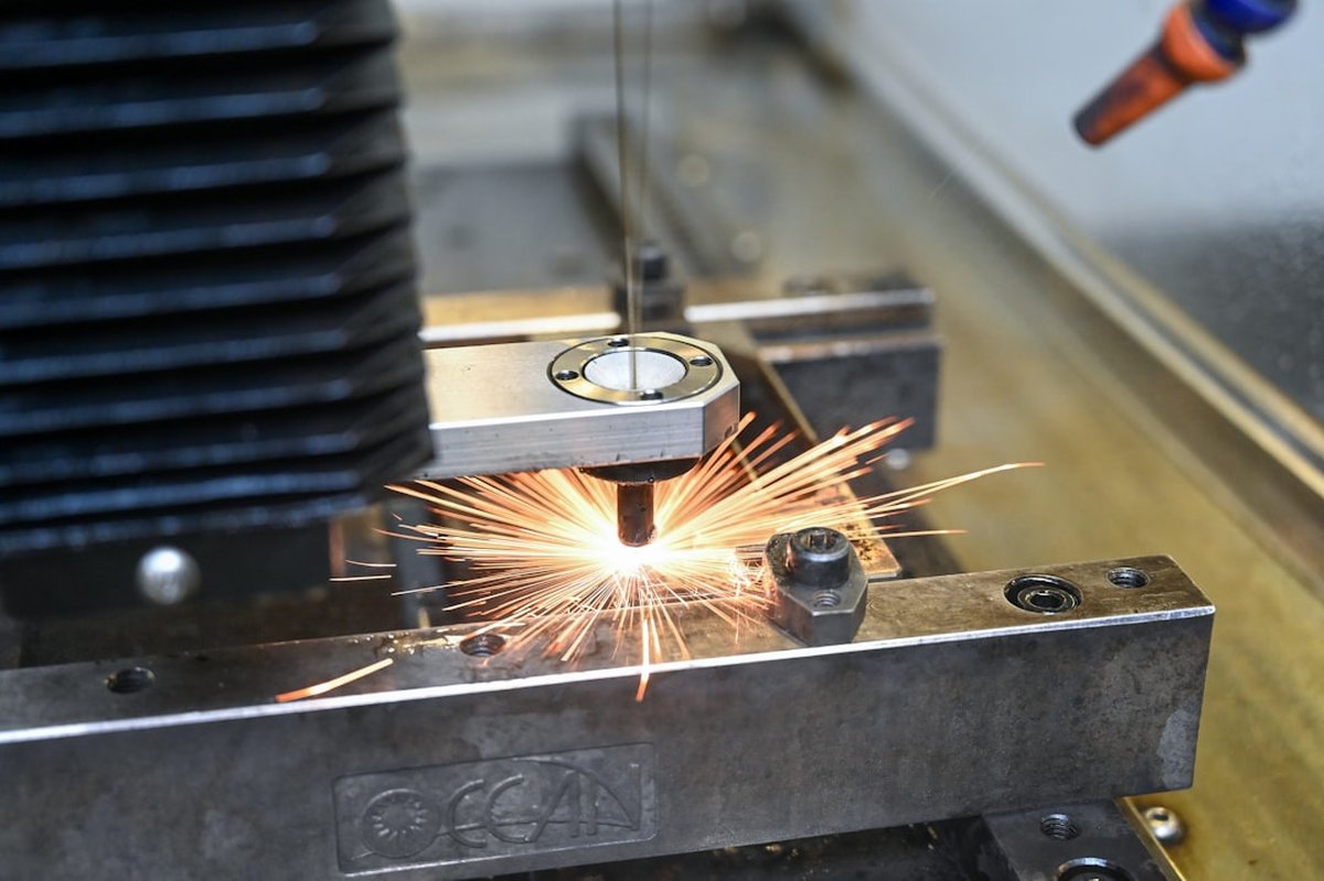
Walk into any high-volume fabrication shop, and you'll notice something interesting: the plasma cutting stations run by veteran operators consistently produce cleaner cuts, faster cycle times, and less post-cut grinding than those run by less experienced hands. The equipment might be identical, but the results aren't even close.
That gap isn't magic—it's technique. After spending two decades in fabrication and interviewing dozens of professional plasma operators, I've compiled the plasma cutting techniques that separate shop-floor experts from everyone else. These aren't the basics you'll find in your owner's manual. These are the hard-won insights that come from cutting thousands of feet of steel, aluminum, and stainless every week.
In this comprehensive guide, you'll learn the advanced plasma cutting techniques professionals use to achieve near-laser edge quality, extend consumable life by 40% or more, and troubleshoot problems before they ruin a part. Whether you're running a handheld torch or programming a CNC plasma table, these secrets will transform your cutting quality and efficiency.

Photo by Andrea De Santis on Unsplash
What Are Plasma Cutting Techniques?
Plasma cutting techniques encompass the methods, settings, movements, and strategies that operators use to optimize cut quality, speed, and efficiency when working with plasma arc cutting systems. While the fundamental physics—ionized gas creating a conductive channel that melts and blows away metal—remains constant, how you apply that technology varies dramatically based on material, thickness, desired edge quality, and production requirements.
At the professional level, plasma cutting techniques extend far beyond simply pulling a trigger or pressing start. They include precise torch height control, optimal travel speed calibration, strategic pierce sequencing, consumable management protocols, and material-specific parameter adjustments. The American Welding Society classifies plasma arc cutting (PAC) as a thermal cutting process, but mastering it requires understanding both the science and the craft.
Professional plasma cutting techniques can be divided into several categories:
-
Material cleaning, workpiece positioning, and ground clamp placement strategies
-
Amperage selection, gas pressure settings, and cut chart interpretation
-
Travel speed, torch angle, and lead-in/lead-out strategies
-
Edge starts, rolling pierces, and stationary pierce methods for various thicknesses
-
Wear monitoring, replacement timing, and storage protocols
-
Dross removal strategies and edge finishing approaches
The difference between amateur and professional plasma cutting often comes down to consistency. A pro doesn't just make good cuts—they make the same quality cut on the first piece and the five-hundredth piece. That consistency comes from understanding how all these technique categories interact and developing systematic approaches to each one.
Why Plasma Cutting Techniques Matter
In a competitive fabrication environment, the quality and efficiency of your plasma cutting directly impacts your bottom line. Proper technique isn't just about making pretty cuts—it's about profitability, safety, and staying competitive in an industry where margins are often razor-thin.
Consider the economics: a fabrication shop cutting 500 parts per day with poor technique might spend an additional 30 seconds per part on grinding and cleanup. That's 250 minutes—over four hours—of non-value-added labor every single day. At a fully burdened labor rate of $45 per hour, that's $180 daily or nearly $47,000 annually in wasted labor. Master the right plasma cutting techniques, and that money goes straight to your bottom line.
Beyond the financial impact, proper plasma cutting techniques matter for several critical reasons:
Part Quality and Fit-Up: Downstream welding and assembly operations depend on accurately cut parts. Poor plasma technique creates beveled edges, excessive dross, and dimensional inaccuracies that cause fit-up problems. When parts don't fit, welders spend time grinding, filling gaps, and making adjustments—all non-productive activities that could have been avoided at the cutting stage.
Safety Considerations: Plasma cutting involves extreme temperatures, molten metal, UV radiation, and potentially hazardous fumes. Proper technique minimizes spatter, reduces the risk of blowback during piercing, and ensures operators maintain safe working distances. The Occupational Safety and Health Administration (OSHA) provides guidelines on metal fume exposure that proper cutting technique helps you meet.
Equipment Longevity: Your plasma system represents a significant capital investment. Poor technique—particularly improper piercing and incorrect amperage settings—accelerates wear on torches, leads, and power supplies. Operators who master proper technique routinely get 50% longer service life from their equipment.
Competitive Advantage: In an era where customers can easily get quotes from multiple shops, the ability to deliver clean, accurate cuts quickly sets you apart. Shops known for quality cutting attract better work at better prices.
How to Master Professional Plasma Cutting Techniques
Mastering professional plasma cutting techniques requires a systematic approach that builds foundational skills before advancing to specialized methods. Here's the proven progression that top fabrication shops use to train their operators.
Step 1: Understand Your Cut Charts
Every plasma system comes with cut charts—and most operators ignore them. This is a critical mistake. Cut charts represent thousands of hours of engineering and testing to determine optimal parameters for specific materials and thicknesses.
Start by studying your system's cut charts thoroughly. Note how amperage, air pressure, torch height, and travel speed change across different material thicknesses. For Hypertherm systems, for example, the cut charts specify different parameters for "production" cuts (maximizing speed) versus "quality" cuts (maximizing edge finish). Understanding when to use each setting is fundamental.
Create a quick-reference card for your most common materials and thicknesses. Laminate it and keep it at your cutting station. Even experienced operators benefit from having verified parameters instantly accessible.
Step 2: Master the Pierce
The pierce is where most plasma cutting problems begin. A poor pierce technique damages consumables, creates excessive spatter, and can even blow holes through thin material. Professional operators use different pierce techniques based on material thickness:
Edge Starts: Whenever possible, start cuts from the material edge rather than piercing. Position the torch at the edge with approximately 1.5x normal standoff distance, initiate the arc, then move onto the workpiece while reducing to normal cutting height. This eliminates pierce wear entirely.
Rolling Pierce (Under 1/2" Material): For thinner materials, use a rolling pierce. Start the arc while moving, allowing the plasma stream to gradually penetrate the material as you travel. This prevents the molten metal from blowing back up into the torch.
Stationary Pierce with Elevated Height (1/2" to 1" Material): For moderate thicknesses, initiate the pierce at 1.5-2x normal standoff distance. Hold position until penetration is complete (listen for the sound change), then lower to cutting height and begin travel.
Pre-Flow Pierce (Over 1" Material): For thick materials, use a pre-flow sequence if your system supports it. This establishes the gas flow pattern before arc initiation, creating a protective gas cushion that shields consumables from blowback.
Photo by Steve Johnson on Unsplash
Step 3: Dial In Your Travel Speed
Travel speed is the single most impactful variable in plasma cut quality, yet it's where operators most frequently make mistakes. Too slow creates excessive dross on the bottom edge and wastes time. Too fast produces a beveled cut with heavy top spatter.
The telltale sign of correct speed is the arc trail angle. When cutting at optimal speed, the arc trails behind the torch at approximately 15-20 degrees from vertical. If the arc is perpendicular to the surface, you're moving too slowly. If it trails at more than 30 degrees, you're too fast.
For CNC operations, start with cut chart speeds and make test cuts on scrap material identical to your production work. Examine the edge quality, kerf width, and dross adhesion. Adjust speed in 5% increments until you achieve optimal results, then document those settings.
For handheld cutting, develop a consistent drag technique. Many professionals use the drag shield method—lightly dragging the shield cup along the workpiece surface. This maintains consistent standoff while providing a speed reference through tactile feedback.
Step 4: Control Your Torch Height
Torch-to-work distance (standoff) directly affects cut quality, kerf width, and consumable life. Most systems specify a standoff between 1/16" and 3/16" depending on amperage and material.
On CNC systems, invest in a quality torch height controller (THC) with arc voltage sensing. The THC automatically maintains optimal standoff by monitoring arc voltage—as the torch gets closer to the work, voltage drops; as it moves away, voltage rises. Set your voltage target based on cut charts and let the THC do its job.
For mechanized systems without automatic height control, use standoff guides or drag shields appropriate to your cutting parameters. Check and adjust before every cut sequence.
Critical insight: Torch height matters most at lower amperages. When cutting thin material at 45 amps, a 1/16" standoff variation dramatically affects cut quality. When cutting 1" plate at 200 amps, the system is more forgiving. Adjust your precision expectations accordingly.
Step 5: Optimize Your Lead-Ins and Lead-Outs
How you enter and exit a cut significantly impacts edge quality at those points. Professional CNC programmers use specific lead-in and lead-out strategies to ensure clean part edges:
Lead-In Types: - Linear lead-ins: Simple angled approach to the cut line. Use 45-60 degree angles with lengths of 0.25-0.5" for most applications. - Arc lead-ins: Curved approach that eliminates the direction change inherent in linear lead-ins. Preferred for thick materials and applications where edge quality is critical.
Lead-In Placement: Always position lead-ins in scrap areas—either outside the part on external contours or inside cutouts on internal features. Never pierce directly on a finished edge.
Lead-Outs: Use lead-outs to prevent the arc from dwelling at the cut completion point. A simple 0.25" overcut past the lead-in intersection point prevents the "witness mark" that occurs when the arc stops on the part edge.
Step 6: Master Direction and Torch Angle
Plasma arcs rotate—typically clockwise when viewed from above on most systems. This rotation creates a fundamental asymmetry: the right side of the kerf (relative to travel direction) produces a squarer edge than the left side, which exhibits more bevel.
Professional CNC programmers exploit this by programming cut direction based on which edge matters:
- External contours: Cut clockwise (climb direction) so the good edge faces the part
- Internal contours: Cut counter-clockwise so the good edge faces the remaining material
For handheld work, understand that the edge on your right (as you face the direction of travel) will be your quality edge. Position your cut path so critical edges benefit from this characteristic.
Torch Angle Considerations: For most cutting, keep the torch perpendicular to the workpiece. However, when cutting bevels or preparing weld joints, precise torch angle control becomes essential. Many mechanized systems offer torch angle adjustment for this purpose.
Common Plasma Cutting Mistakes to Avoid
Even experienced fabricators develop bad habits that compromise their plasma cutting results. Here are the most common mistakes I see when visiting shops—and how to correct them.
Mistake 1: Ignoring Consumable Wear
Consumables don't fail suddenly—they degrade gradually. Many operators run consumables until cut quality becomes unacceptable, not realizing they've been producing subpar cuts for hours or days before reaching that point.
The fix: Implement a consumable inspection protocol. Check electrodes and nozzles at the beginning of each shift and after every 2-3 hours of cutting. Look for pit depth on electrodes (replace when the pit exceeds manufacturer specifications, typically 1/16" to 3/32") and examine nozzle orifices for erosion, gouging, or ovality.
Track your consumable usage by recording starts and cut time. Over time, you'll develop reliable prediction models for when replacement is needed—before quality suffers.
Mistake 2: Wrong Amperage Selection
More power isn't always better. Many operators default to maximum amperage, thinking it will cut faster and cleaner. In reality, excessive amperage for the material thickness creates wider kerfs, more dross, and dramatically shortened consumable life.
The fix: Match amperage to material thickness using cut charts. As a general rule, use approximately 20 amps per 1/16" of mild steel thickness (with variations for different materials). For a 1/4" steel plate, 80 amps is typically ideal—not 100 or 120.
When in doubt, test. Make sample cuts at different amperages on scrap material and examine the results. Often, reducing amperage by 10-15% from your current setting will improve cut quality while extending consumable life.
Mistake 3: Inadequate Work Clamp Connection
The work clamp (ground clamp) is half of your electrical circuit, yet it's frequently neglected. Poor ground connections create unstable arcs, inconsistent cut quality, and can even damage your power supply.
The fix: Connect the work clamp directly to the workpiece or cutting table—not to a painted surface, not to a distant point on a long table, and never through multiple metal-to-metal contact points. Clean the connection area to bare metal. For large cutting tables, consider multiple work clamp connections or a dedicated copper bus bar system.
Inspect your work clamp and cable regularly. Look for frayed cables, damaged clamp jaws, and loose connections. Replace worn clamps immediately—the cost is minimal compared to the quality and equipment problems they cause.
Mistake 4: Neglecting Air Quality
Plasma cutting requires clean, dry air. Moisture, oil, and particulates in the air supply create porous cuts, excessive spatter, and premature consumable failure. This is especially critical in humid climates or shops with older compressed air systems.
The fix: Install a dedicated air treatment system for your plasma cutter. At minimum, this should include a coalescing filter to remove oil aerosols and a refrigerated dryer or desiccant dryer to remove moisture. The Compressed Air and Gas Institute recommends air quality meeting ISO 8573-1 Class 1.4.1 for plasma cutting applications.
Drain water traps daily. Replace filter elements according to manufacturer schedules—and more frequently in challenging environments. Consider installing a point-of-use filter/dryer assembly immediately before the plasma unit as a final safeguard.
Mistake 5: Inconsistent Travel Speed
Human operators naturally vary their travel speed—slowing at corners, speeding up on long straight runs, and hesitating at the beginning of cuts. This inconsistency creates visible variations in cut quality.
The fix: For handheld cutting, use mechanical guides whenever possible. A straight edge clamped to the work makes maintaining consistent speed much easier than freehand cutting. For circles, use a radius bar or circle cutting attachment.
For CNC systems, avoid the temptation to override programmed speeds during cutting. If you find yourself consistently adjusting speeds, the underlying program parameters need revision—not real-time operator intervention.
Practice making consistent cuts on scrap material. Use a stopwatch to time your travel over measured distances. Work toward achieving the same travel speed (±10%) repeatedly before progressing to production work.
| Problem | Likely Cause | Solution |
|---|---|---|
| Excessive top spatter | Travel speed too fast | Reduce speed by 10-15% |
| Heavy bottom dross | Travel speed too slow or amperage too high | Increase speed or reduce amperage |
| Beveled cut edge | Travel speed too fast or worn consumables | Reduce speed and inspect consumables |
| Arc wandering | Worn nozzle or contaminated air | Replace consumables, check air quality |
| Hard-to-remove dross | Standoff too high or amperage too low | Decrease standoff or increase amperage |
| Inconsistent arc | Poor ground connection | Clean and secure work clamp connection |
Best Practices from Professional Fabricators
Beyond avoiding common mistakes, professional plasma operators employ specific best practices that elevate their work. These techniques separate competent operators from true experts.
Consumable Break-In Protocol
New consumables require a break-in period to achieve optimal performance. Professional operators never install new consumables and immediately begin production cutting.
The break-in protocol: 1. Install new electrode and nozzle 2. Make 3-5 short cuts (6-12" each) at 75% of normal amperage 3. Allow consumables to cool for 2-3 minutes 4. Increase to normal production amperage
This gradual introduction allows the consumable materials to seat properly and develop the initial pit in the electrode center under controlled conditions. Skipping break-in often results in off-center pitting that reduces consumable life by 25-40%.
Material Preparation Standards
Surface condition dramatically affects plasma cut quality, yet many shops cut whatever comes off the truck without preparation. Professional shops implement material prep standards:
For mill scale steel: Light scale is acceptable for most production cutting. Heavy, flaky scale should be removed from the cut path with a grinder or wire wheel—the cutting path only, not the entire sheet.
For oily or contaminated surfaces: Wipe the cut path with acetone or a dedicated metal prep solvent. Oil causes erratic arcs and increased spatter.
For rusty material: Light surface rust is generally acceptable. Heavy rust should be removed from the cut path. Consider running 5-10% slower on rusty material as the oxidized surface affects arc stability.
For aluminum: Remove the oxide layer from the cut path immediately before cutting. Aluminum oxide has a much higher melting point than the base metal and can cause erratic cutting.
I tell every new operator the same thing: your plasma cutter doesn't know what's coming next—but you do. Think two cuts ahead, plan your sequences, and you'll eliminate half your problems before they start.
Strategic Cut Sequencing
The order in which you make cuts on a part or sheet affects both quality and efficiency. Professional CNC programmers spend significant time optimizing cut sequences:
Inside features first: Always cut internal features (holes, slots, cutouts) before external contours. This maintains sheet rigidity during the most precision-critical operations.
Small to large: When cutting multiple internal features, cut smaller features before larger ones. Small features are most affected by heat distortion, so cutting them while the material is coolest produces the best accuracy.
Strategic traverses: Minimize torch travel over hot areas. Program traverse paths to avoid crossing recently cut areas where the heat might affect torch height control or cause tip-ups.
Common-line cutting: When adjacent parts share an edge, cutting that edge once (common-line cutting) saves time and material. However, this technique requires careful setup to ensure both parts remain properly supported throughout the sequence.
Temperature Management
Plasma cutting generates significant heat, and thermal effects accumulate during extended cutting sessions. Professional operators manage workpiece temperature to maintain dimensional accuracy:
Allow cooling between passes: When making multiple cuts on the same part, allow the material to cool between operations—especially for precision work. A 5-minute cooling period between heavy cuts can prevent distortion issues.
Use skip-cutting patterns: On large nested sheets, program the cutting sequence to skip around the sheet rather than cutting adjacent parts consecutively. This distributes heat more evenly and reduces localized distortion.
Monitor ambient conditions: Extreme shop temperatures affect both equipment and materials. In cold conditions, allow equipment to warm up fully before production. In hot conditions, be aware that materials will expand more and thermal effects will be more pronounced.
Documentation and Continuous Improvement
Top-performing shops treat plasma cutting as a process to be optimized, not just a task to be completed. They document everything:
- Record optimal parameters for each material type and thickness
- Track consumable life under different operating conditions
- Log problems and solutions for future reference
- Photograph cut quality standards for operator training
This documentation transforms individual operator knowledge into organizational capability. When your best operator is out sick, documented procedures ensure consistent quality continues.
-
Check drains, filters, and pressure readings
-
Check electrode pit depth and nozzle condition
-
Clean metal contact, secure attachment
-
Verify parameters on material matching production work
-
Record what worked for future reference
-
Remove spatter and debris, inspect for wear
Advanced Techniques for Specific Applications
Once you've mastered fundamental plasma cutting techniques, specialized applications require additional knowledge. Here are advanced approaches for common challenging scenarios.
Cutting Stainless Steel
Stainless steel presents unique challenges due to its lower thermal conductivity and tendency to work-harden. Professional approaches include:
Gas selection: Switch from compressed air to nitrogen or a nitrogen/hydrogen mixture for stainless. Air cutting works but creates an oxidized edge that may require removal before welding. Nitrogen produces a cleaner edge that's often weld-ready.
Speed adjustments: Reduce travel speed by 10-15% compared to mild steel of the same thickness. Stainless doesn't conduct heat away from the cut zone as efficiently, so slower speeds compensate.
Post-cut treatment: For applications requiring maximum corrosion resistance, passivate the cut edge or remove the heat-affected zone mechanically. The heat from cutting can deplete chromium in the edge zone, reducing corrosion resistance.
Cutting Aluminum
Aluminum's high thermal conductivity and reflectivity require technique modifications:
Increased amperage: Use approximately 25% more amperage for aluminum compared to steel of equal thickness. The heat dissipates quickly, requiring more energy input.
Nitrogen or argon/hydrogen shielding: For best results, use nitrogen or an argon/hydrogen mix. These gases produce cleaner cuts with less dross than compressed air.
Faster travel speeds: Despite the higher amperage, travel speeds for aluminum are typically 20-30% faster than steel. The material melts and blows away readily once sufficient energy is applied.
Fixturing considerations: Aluminum sheets tend to lift and vibrate during cutting due to their light weight. Secure fixturing or strategic weighting prevents movement that causes quality issues.
High-Definition Plasma Cutting
High-definition (HD) plasma systems achieve cut quality approaching laser cutting but require more precise technique:
Tighter tolerances on everything: HD plasma demands stricter adherence to specified parameters. Standoff variations of just 0.010" that would be acceptable in conventional plasma create visible quality variations in HD cutting.
Gas mixing precision: HD systems often use precise gas mixtures (such as oxygen/nitrogen or argon/hydrogen blends). Ensure your gas delivery system maintains specified ratios—minor variations affect cut quality.
Consumable alignment: HD torches require precise consumable alignment. Follow manufacturer procedures for consumable installation exactly—the tight tolerances that enable HD performance are unforgiving of sloppy assembly.
Reduced pierce heights: HD systems typically use lower pierce height ratios than conventional systems. Follow cut charts precisely rather than applying conventional plasma experience.
Bevel Cutting
Creating beveled edges for weld preparation requires additional technique considerations:
Angle compensation: Most plasma arcs naturally create a slight bevel (typically 1-3 degrees on the "good" side). When cutting specific bevel angles, compensate for this inherent characteristic.
Speed reduction: Bevel cutting removes more material per linear inch of travel. Reduce travel speed by approximately 15-20% compared to straight cuts at the same material thickness.
Dual-head considerations: For production bevel cutting, dedicated bevel heads that tilt the entire torch assembly produce better results than beveling with torch manipulation alone.
Multi-pass strategies: For heavy bevels (over 45 degrees) or thick materials, multiple passes at different angles may produce better results than single-pass cutting.
Photo by Trophim Laptev on Unsplash
Selecting the Right Equipment for Your Application
Even perfect technique can't overcome equipment limitations. Matching your plasma system to your application is essential for professional results.
Amperage and Capacity Selection
Select system amperage based on your maximum expected material thickness, not your average work. While you can cut thicker material at reduced quality, you cannot cut above your system's rated capacity.
General guidelines for mild steel cutting capacity: - 45-amp systems: Up to 1/2" production quality, 5/8" maximum severance - 65-amp systems: Up to 3/4" production quality, 7/8" maximum severance - 85-amp systems: Up to 1" production quality, 1-1/4" maximum severance - 105-amp systems: Up to 1-1/4" production quality, 1-1/2" maximum severance
For production environments, select a system with capacity exceeding your regular needs. Running a plasma system at 90%+ of its rated capacity continuously shortens equipment life and reduces cut quality consistency.
Duty Cycle Considerations
Duty cycle indicates how long a system can operate continuously before requiring cooling. A 60% duty cycle at rated amperage means the system can cut for 6 minutes out of every 10-minute period.
For production cutting, prioritize systems with 60% or higher duty cycles. High-production environments may justify 100% duty cycle industrial systems despite their higher cost.
Remember that duty cycle is typically rated at maximum amperage. Operating at reduced amperage increases effective duty cycle—a system rated at 60% duty cycle at 100 amps may achieve near-100% duty cycle at 60 amps.
- Lower initial cost for inverter-based systems
- Portable systems available for field work
- Modern systems offer excellent cut quality even at lower price points
- CNC compatibility available across most system classes
- Higher-quality systems have higher upfront costs
- Consumable costs vary significantly between brands
- Maximum thickness capacity limits future flexibility
- Power requirements may necessitate electrical upgrades
CNC vs. Handheld Applications
The choice between CNC and handheld plasma cutting depends on your production requirements:
CNC plasma advantages: Repeatability, complex shapes, nested cutting efficiency, minimal operator fatigue, consistent quality across large production runs.
Handheld advantages: Lower capital cost, flexibility for field work, ability to cut in any position, simpler maintenance, faster setup for one-off parts.
Many shops maintain both capabilities—CNC tables for production work and handheld systems for maintenance, repair, and prototype work. If budget permits only one, choose based on where you'll make the majority of your cuts.
Plasma Cutting Techniques FAQ
Conclusion
Mastering professional plasma cutting techniques transforms this essential fabrication process from an art practiced by a few into a repeatable system that delivers consistent, high-quality results. The secrets we've covered—from proper pierce techniques and travel speed optimization to consumable management and material-specific approaches—represent the accumulated wisdom of thousands of hours at the cutting station.
The path to plasma cutting excellence isn't complicated, but it requires commitment. Start with the fundamentals: study your cut charts, master the pierce, and learn to read the arc trail angle. Build systematic habits around consumable inspection, air quality monitoring, and workpiece preparation. Document what works and continuously refine your approach.
Remember that even the most experienced plasma operators are still learning. New materials, evolving equipment technology, and changing application requirements mean there's always room for improvement. The best fabricators I know approach every cutting session as an opportunity to get a little better at their craft.
Your plasma cutting system is a precision tool capable of producing remarkable results. Apply the techniques in this guide consistently, and you'll join the ranks of fabricators who make it look easy—because for them, it has become exactly that.
Expand Your Welding Knowledge
Ready to take your fabrication skills to the next level? Explore our comprehensive welding guides covering MIG, TIG, and stick welding techniques used by professional fabricators.
Browse Welding Guides
Comments
No comments yet. Be the first to comment!
Leave a Comment