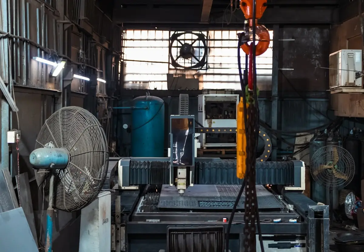
Process selection on a print comes down to three questions: what shape the feature is, how tight it has to be, and whether the material is hard. Toolpath strategy, axis count and operation order all follow from those answers. This page is the reference for the techniques a job shop runs day to day: milling in its conventional and climb directions plus trochoidal and adaptive roughing, turning with and without live tooling, drilling and boring, grinding, wire and sinker EDM, and the difference between 3+2 positioning and simultaneous five-axis motion.
The thing most people get wrong is treating these as a ladder of sophistication with five-axis at the top and drilling at the bottom. They are not ranked, they are assigned, and the assignment is made by the tolerance and the geometry. The corollary, which the process engineers say more bluntly than the salespeople do, is that most of the cost on a tight print was never required by the part. Modus Advanced's process-selection guide calls tolerances tighter than function one of the most common design mistakes in manufacturing, and puts a number on it: moving a feature from the standard tier into the high-precision tier adds 200 to 400 percent to cost and 100 to 200 percent to lead time (undated page, retrieved September 2026).
Four removal mechanisms, and what each one buys
Everything in a machine shop removes material one of four ways: a rotating multi-flute tool against a fixed workpiece, a fixed single-point tool against a rotating workpiece, a bonded abrasive taking many shallow cuts, or a spark eroding material with no mechanical contact at all. Each mechanism has a tolerance ceiling, a geometry it fits, and a cost per feature. The rest is detail.
Milling cuts intermittently. Every tooth enters, loads, and leaves, which is why milling is the process that chatters and why so much of milling practice is about controlling engagement rather than maximizing depth. Direction matters: in climb milling the cutter rotation runs with the feed and chip thickness starts thick and thins out, which loads the machine consistently and pushes the tool away from the wall; in conventional milling the tooth starts at zero thickness and rubs before it cuts, which is forgiving of hard scale and of a machine with backlash in the screws and unkind to tool life everywhere else. Trochoidal and adaptive clearing are not different mechanisms, they are engagement management: a small radial step taken at full axial depth, with the tool path looping so the engagement angle stays roughly constant instead of doubling in a corner. Note what that buys. It buys tool life, deeper axial engagement and predictable spindle load. It does not tighten a tolerance, and none of the published tolerance tables distinguish an adaptive-roughed pocket from a full-width one, because the finish pass is what decides the number.
Turning gets concentricity for free, because every diameter is cut about the same axis of rotation. That is the whole reason turning exists as a separate discipline, and Protolabs Network's tolerance notes state the practical result: turning typically holds tighter tolerances more cost-effectively than milling on cylindrical features such as roundness and concentricity, while milling wins on complex geometry, hole patterns and positional relationships across multiple faces. Live tooling blurs the line by letting you add milled features inside the turning setup, which is a setup-count win rather than an accuracy win, although on a part where the milled feature must be located from a turned datum the two amount to the same thing.
Drilling and boring are usually discussed together and should not be. A drill produces a hole roughly where the spindle was, with size and straightness coming largely from the tool itself. Boring produces size, roundness and location from the machine's axis using a single point, which is why precision boring sits in the same tolerance tier as grinding rather than in the same tier as drilling.
Grinding is a finishing operation, full stop. Modus describes it as applying where the tolerance exceeds standard milling capability, and notes the cost of that: separate operations and handling time. The interesting development of the last year is machine builders attacking exactly that handling cost. Mazak's INTEGREX i-350S NEO is the first machine in that series to add grinding alongside turning and milling, and the company's stated pitch is finishing to exacting tolerances without a second setup (Mazak press release, machine debuted at DISCOVER 2025, October 6 to 10, 2025).
EDM removes material thermally and applies no cutting force, so hardness is irrelevant to it. Modus is direct about when it is the answer: it is the correct process for sharp internal corners where cutting tools break, and for hardened material where a cutter would wear out or shatter. It is also slower and more expensive than the milling alternative, which is why nobody chooses it for fun. Wire EDM threads a traveling electrode through the work and cuts through-profiles and tapers; sinker EDM burns a formed electrode down into a blind cavity, which is how mold detail and square-bottomed pockets get made. The sources collected here do not split achievable tolerance by EDM type, so treat published EDM figures as covering the family.
| Fact | Milling | Turning | Grinding / precision boring | EDM |
|---|---|---|---|---|
| Tolerance tier without secondary ops (Modus Advanced, retrieved Sept 2026) | ±0.05 to 0.13 mm (±0.002 to 0.005 in) on finish passes | Same tier as milling, reached more cheaply on diameters | ±0.013 to 0.025 mm (±0.0005 to 0.001 in) | Below ±0.005 mm (±0.0002 in), grouped with lapping and specialized grinding |
| Benchmark and practical limit (PrecisionAM, retrieved Sept 2026) | ±0.005 in (0.13 mm) standard; ±0.001 in near the limit without secondary ops | ±0.005 in standard; ±0.0005 in on Swiss-type diameters, ±0.0002 in on critical features | The process you add when ±0.001 in is not enough | Used where the limit is material hardness or corner geometry rather than resolution |
| Geometry it fits (Protolabs Network, retrieved Sept 2026) | Prismatic parts, pockets, 3D contoured surfaces, hole patterns across faces | Rotationally symmetric work: shafts, bores, faces, grooves | Flats, diameters and bores already brought close by machining | Through-profiles, blind cavities, thin ribs and anything already hardened |
| Sharp internal corner (Modus Advanced) | Cannot cut a true 90 degrees; 0.13 mm (0.005 in) minimum radius, 0.76 mm (0.030 in) recommended | Same constraint on any live-tool milled feature; turned corners follow insert nose radius | Not the process used for internal corners in these sources; it finishes surfaces, not corners | The correct process for sharp internal corners where cutting tools break |
| Hardened material | Tool wear and breakage are the cited limit | Tool wear and breakage are the cited limit | Not quantified in these sources; treated as a finishing operation regardless of hardness | Unaffected; the reason EDM exists after heat treat |
| Cost and schedule effect (Modus Advanced) | Baseline; five-axis milling carries a meaningful cost and schedule premium over three-axis | Lowest cost route to a tight cylindrical feature | Adds separate operations and handling time | Slower and more expensive than milling alternatives |
| Where it sits in the order | Primary, and usually the operation that establishes datums | Primary on round stock; live tooling folds in secondary features | After machining, and after heat treat if there is one | After heat treat, or wherever a cutter physically cannot go |
Working a print into a process, step by step
This is the sequence a programmer runs before the first tool is picked. It looks bureaucratic written down. It takes an hour on a simple part and it is the hour that prevents the second setup nobody quoted.
-
The print, with its governing tolerancing standard identified
ASME Y14.5 for US drawings, currently Y14.5-2018 and reaffirmed without technical change as Y14.5-2018 (R2024), or an ISO block. The edition matters because it governs interpretation of the 14 geometric characteristic symbols.
-
Material condition and heat treat state, with the order of operations already decided
Whether a feature is cut before or after hardening decides whether it belongs to a cutter, a wheel or an electrode.
-
Quantity and due date
Volume changes the machine, not just the schedule. A multitasking lathe suits high-mix low-volume; a multi-spindle suits the opposite.
-
Tool library with real geometry, not catalog nominal
Corner radii in the library are what your CAM will use to decide whether a pocket corner is legal.
-
Workholding plan and datum scheme
Decide which face carries the datums before deciding the setups, not after.
-
Gaging that resolves the tier you are quoting
A ±0.0005 in feature checked with an instrument that reads to 0.001 in is a guess with paperwork.
1. Establish which tolerance rules apply to unmarked dimensions. ISO 2768-1 defines defaults for dimensions with no stated tolerance, in four classes: fine, medium, coarse and very coarse. Protolabs Network publishes its own defaults as an example of how a shop applies them, class f for metals and class m for plastics (retrieved September 2026). Note the ceiling: ISO 2768 does not cover tolerances at or below ±0.01 mm, and PrecisionAM's standards overview states that features that tight need explicit ISO 286 grades, of which there are 20 running IT01 to IT18, with lower numbers tighter. Worked when: every feature on your process sheet has a number and none of them says "shop standard". Costs: an hour, against a first-article dispute.
2. Sort features by geometry into two lists and a problem pile. Rotational features to turning, prismatic and contoured features and multi-face hole patterns to milling. The problem pile is everything that is neither: true sharp internal corners, features that only exist after heat treat, blind square cavities. That pile is your EDM and grinding list, and it is better discovered now than during the quote review. Worked when: the problem pile is explicitly priced rather than assumed away.
3. Assign a tolerance tier to each feature and write it down. Four tiers, per Modus: standard turning and milling at ±0.25 mm (±0.010 in), precision finish milling and turning at ±0.05 to 0.13 mm (±0.002 to 0.005 in), grinding and precision boring at ±0.013 to 0.025 mm (±0.0005 to 0.001 in), and lapping, EDM and specialized grinding below ±0.005 mm (±0.0002 in). Remember that tolerance scales with size. Under a fine-class default, a metal feature between 0.5 and 6 mm gets ±0.05 mm while one between 1000 and 2000 mm gets ±0.5 mm, so a flat ±0.1 mm note means very different things at the two ends of a large part. Worked when: your tier list contains fewer tight features than the print implied.
4. Count setups and fix the datum chain. Each setup is an opportunity to lose a relationship between two features, so the features that share a positional tolerance want to be cut in the same setup. Live tooling on the lathe collapses turned and milled features into one; a multitasking machine can go further. Mazak's INTEGREX i-350S NEO adds internal, external and finishing grinding to turning and milling on one platform, with a 10 inch chuck, main and second turning spindles at 4,000 rpm, a 12,000 rpm milling spindle rated 24 hp (22 kW), 12 in of Y travel, 27 in of X, and a maximum part diameter of 26.38 in (670 mm), per Modern Machine Shop's writeup. Worked when: you can name which face carries each datum and which setup cuts it. Costs: setups are the single largest line item you control at this stage.
5. Choose between 3+2 and simultaneous five-axis on purpose. 3+2 orients the part, locks the rotaries and cuts with three axes, which means a short rigid tool, a straightforward post and predictable surface quality. Simultaneous five-axis earns its keep on continuous contours, undercuts and shapes where tool orientation must change during the cut. PrecisionAM notes that five-axis milling routinely holds ±0.001 in or tighter on complex 3D contours; Modus notes the flip side, a meaningful cost and schedule premium over three-axis. Shops that run 3+2 profitably tend to standardize a handful of 5-axis setup shortcuts and apply them to every job rather than reinventing the orientation scheme per part. Worked when: you can state in one sentence why the rotaries need to move during the cut. If you cannot, they do not.
6. Rough with engagement control, not depth heroics. Adaptive or trochoidal paths at full axial depth and small radial step keep the load steady and keep the corners from spiking. The metric to watch is the spindle load trace, which should be flat and boring. Two vendors now sell products aimed at that same trace: Mazak's SMOOTH Ai Spindle, which the company says optimizes spindle speed from sensor feedback to reduce vibration, and Lambda Function's energy-based tool life prediction from spindle load monitoring. Both are vendor claims. Verifying either independently means running the same tool, part and stock with the feature on and off and comparing tool life and measured finish, which neither company publishes. Worked when: consistent chip color and load, no witness marks left in the corners for the finish pass to chase.
7. Finish with a separate tool, light radial engagement, and one cutting direction. The default outcome of an as-machined surface is Ra 3.2 µm (126 µin) per Protolabs Network; anything better is a specification with a cost attached, not an expectation. Flute count, coating and helix drive what that surface looks like, and choosing carbide end mills per material is where finish and tool life are decided rather than in the feed override. Worked when: the finish number comes off the part, not off the toolpath preview.
8. Drill, then bore or ream anything that has to be located or round. Precision boring reaches ±0.013 to 0.025 mm (±0.0005 to 0.001 in), the same tier as grinding, without the separate machine. If the print's hole tolerance is inside that band, boring is usually the cheaper answer. Worked when: bore size repeats across the run without adjusting the insert between parts.
9. Route to grinding only what the tier requires, and leave the right stock. Grinding is a finishing-only operation that adds handling, and stock left for it has to be uniform or the wheel just transfers the previous operation's error. This is the step where single-setup mill-turn-grind machines change the math, since the handling cost is what they remove. Worked when: grinding stock measures the same at both ends of the feature.
10. Hand the impossible features to EDM. Sharp internal corners, hardened material, thin sections a cutter would push. Wire for through-profiles, sinker for blind detail. Budget it as slower and dearer than milling, because it is. Worked when: the corner on the part matches the corner on the model, which is the only reason you are paying for it.
11. Prove the program before it touches a fixture. Digital twins are the current vendor answer here: Siemens shows its NX X Manufacturing Virtual Machine validating a process virtually to remove collision risk, and Mazak ships MAZATROL TWINS with synchronized digital twins on the SmoothAi control. The figure being circulated is Siemens', for machine onboarding rather than for a single program: 6 to 10 weeks of physical setup and testing reduced to roughly two weeks (as reported in coverage of Siemens' IMTS 2026 program). Verifying it means timing your own onboarding on a comparable machine, which nobody does twice. Worked when: the first run produces chips, not a crash report.
12. Inspect the first article with instruments capable of the tier. Tight tolerance work fails at the gage more often than at the spindle, and the measuring tools machinists overlook are usually the ones that would have caught the form error rather than the size error. Worked when: the measurement repeats when a second person takes it.
Where it goes wrong
Tolerance specified tighter than the function. Modus Advanced names this outright: "Tolerances tighter than standard should appear on a drawing only when the function of the part genuinely requires them." You recognize it when a print carries a blanket tight block instead of tight callouts on the two features that mate. What to do is unglamorous: go back to the customer with the specific features and the specific multiplier, because PrecisionAM's figures show moving from ±0.010 in to ±0.005 in often doubles machining cost and reaching ±0.001 in runs 3 to 5 times baseline.
A true sharp internal corner in the model. End mills cannot cut one, and the numbers are published: minimum internal corner radius for milling is 0.13 mm (0.005 in) with 0.76 mm (0.030 in) recommended; deep pockets want 0.25 mm minimum and 1.52 mm (0.060 in) recommended; thin wall features 0.51 mm minimum and 2.03 mm (0.080 in) recommended (Modus, retrieved September 2026). You recognize it when CAM silently substitutes the tool radius, or when the quote comes back with an unexplained EDM line. Fix it in the model with a legal radius, or price the EDM.
Using ISO 2768 defaults on sub-0.01 mm features. The standard does not reach there. If the block says class f and the feature is a ±0.005 mm bore, the print does not actually tolerance that bore, and two shops will interpret it two ways. Specify the ISO 286 grade, or apply the geometric controls in ASME Y14.5.
Treating grinding as a rescue. Grinding called in after a milled feature misses is grinding with uneven stock, on a part that has already left its fixture. You recognize it in the routing sheet as an operation added in pen. Plan it as its own operation with stock allowance from the start, or move the feature to a machine that grinds in the turning setup.
Buying simultaneous five-axis motion for a 3+2 problem. The premium is real and it is charged per part in cycle time and per program in verification effort. The tell is a five-axis program whose rotaries move only between features. There is nothing wrong with that program, but it did not need a five-axis budget.
Believing a headline spindle figure. The same Mazak machine appears with an optional milling spindle of 20,000 rpm in the company's own release and in Modern Machine Shop's coverage, and 24,000 rpm in Cutting Tool Engineering's writeup. One of those is a transcription error, and from outside you cannot tell which. The stable numbers across all three are the 12,000 rpm standard spindle and the 24 hp (22 kW) rating, and the rating is the one that decides whether you can take the cut. Ask for the option code and the power curve.
Taking AI programming claims at their stated value. Lambda Function, exhibiting at IMTS 2026, claims CNC programming time drops from multiple days to hours using feature recognition from CAD, adaptive toolpath generation and a model that learns each machinist's tool, speed and feed choices, and is currently free for machinists, per IMTS's own writeup. FANUC's next-generation 500i-A control demonstrates automatic programming directly from CAD models. Siemens' Make Machining Suggestion recommends strategies drawn from a shop's historical data, which means a shop without clean historical data has nothing for it to draw on. Programming hours saved is the easiest metric to show and the least interesting one. The number to compare is posted cycle time and scrap on the same part family programmed both ways. The company's own CEO frames the rollout in terms of earned trust rather than proven output:
The technology needs to earn the user's trust. Once they start trusting it, they can choose to relinquish control and unlock autonomy, but they won't be forced down a certain path.
When the rules are different
Small diameters on a Swiss-type. The "±0.001 in is about the practical limit for turning without secondary operations" rule does not hold here. PrecisionAM puts Swiss-type capability at ±0.0005 in on turned diameters and ±0.0002 in on critical features, which is grinding-tier and better on a single machine. If the part is a small shaft with tight diameters, the process question is whether a Swiss is available, not whether to add a grind.
Plastics. Default tolerance classes diverge from metal. Protolabs Network's published defaults are class f for metals and class m for plastics, which puts a 0.5 to 6 mm plastic feature at ±0.1 mm against ±0.05 mm in metal, and a 1000 to 2000 mm plastic feature at ±1.2 mm against ±0.5 mm. Apply the metal numbers to a plastic part and you will be arguing with a part that moved after you measured it.
Large parts. Tolerance bands widen with dimension range by design, from ±0.05 mm at the small end of the fine-class table to ±0.5 mm at 1000 to 2000 mm. A tight geometric callout on a long part is a thermal and fixturing problem more than a cutting one.
Anything at or below ±0.01 mm. Different standards apply, as above. PrecisionAM's translation is the useful anchor: "±0.001 in. (0.025 mm) on a 10 mm diameter feature corresponds to IT6 territory" in ISO 286 terms.
Older prints. Y14.5-2018 was, in the standards community's own description, a turning point for the standard, and it was reaffirmed without technical change as Y14.5-2018 (R2024). A drawing released against an earlier edition is interpreted against that earlier edition, so check the revision block before you argue about a datum reference frame.
Features that only exist after heat treat. The tier table stops being the deciding factor and hardness takes over. Cutters are out, wheels and electrodes are in, and the corner radius constraints that governed the milled version no longer apply to the EDM'd one.
High volume versus high mix. Multitasking machines are sold on unattended runtime for high-mix, low-volume work, with pallet pools and bar feeders quoted as supporting up to 72 hours unattended in AMT's IMTS 2026 preview. Volume work goes the other direction: Index debuted its MS24-8 CNC multi-spindle lathe with eight spindles at the same show. Okuma launched the Multus U1000 and U2000 mill-turn centers with full five-axis interpolation, and brought 11 machines to Chicago with 9 of them paired to automation and a new Tower Pallet Changer holding 13 pallets, per Fabricating & Metalworking. The direction of travel is that automation is no longer an option line on the quote, which changes the setup math for small shops more than any toolpath development has in years.
The cost of another decimal place
Read those four figures as a single curve rather than four facts. The jump from standard to precision roughly doubles cost; the jump from precision to grinding-tier roughly triples to quintuples it; the jump past that is not a jump, it is a different business. Two independent sources arrive at similar multipliers from different directions, which is about as much agreement as this industry produces on pricing.
The finish figure belongs in the same conversation. Ra 3.2 µm (126 µin) is the standard as-machined result; better than that means either a finishing pass with its own cycle time or a secondary process, and the three families available are removal finishes such as polishing and brushing, build-up finishes such as anodizing, powder coating and plating, and abrasive finishes such as bead blasting (Protolabs Network, retrieved September 2026).
For the machine side of the ledger, AMT's IMTS 2026 material sizes the market the technique choices are being made in: a US manufacturing economy of $2.95 trillion, $10.5 trillion in combined domestic and foreign manufacturing investment, and $37.1 billion of output in the machine shop segment specifically, with manufacturing technology orders growing in 2025 for the first annual growth since 2021. A blog covering Siemens' IMTS program cites 28.9 percent order growth without naming the period or the series it belongs to, so treat that figure as unsourced until someone attaches it to a month. The show itself ran September 14 to 19, 2026 at McCormick Place across more than 1.2 million square feet with over 1,800 exhibitors, and AMT's own framing of it was that the software is now the story:
IMTS showcases how AI, software, automation, and other digital solutions advance the capabilities of machine tools.
Which is fair, and worth keeping in proportion. None of the control-side announcements from the 2026 cycle, FANUC's 500i-A with its CAD-driven automatic programming and tool management, Siemens' Machining Copilot, Mazak's Ai Thermal Shield, changes a tolerance tier. They change how long it takes to get to the tier and how reliably you stay there. The tiers themselves are set by the mechanism, and the mechanism has not moved.
Comments
No comments yet. Be the first to comment!
Leave a Comment